
Variables
Description
What is this formula?
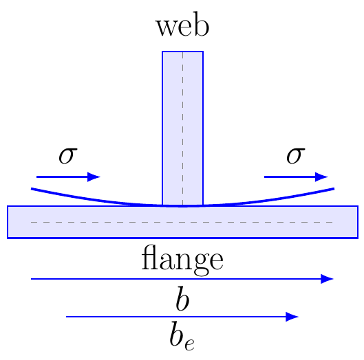
The shear lag factor relates the effective flange width to the actual flange width in a structural member. It accounts for the nonuniform longitudinal stress distribution that can occur in wide flanges, box girders, thin-walled sections, and tension members.
When to use it
Use this formula when only part of the actual width of a flange or plate is fully effective in carrying longitudinal stress. It is commonly used in steel design, bridge girders, box sections, and connection design.
Example
A steel flange has:
be = 0.75 m
b = 1.00 m
Formula:
U = be / b
Substitution:
U = 0.75 / 1.00
Result:
U = 0.75
This means that 75% of the actual flange width is effective for the considered stress distribution.
Applications
Steel bridge design, box girders, wide flange plates, thin-walled sections, tension members, welded connections, and effective width calculations.
Note
This formula expresses the shear lag factor as a simplified effective-width ratio. In design codes, the effective width and shear lag factor may depend on member length, connection details, load path, boundary conditions, and code-specific reduction rules.